
Boiler feed pumps are likewise alluded to as take care of siphons (see Reactor siphon) and planned as multistage spiral stream siphons. (Additionally see Multistage siphon)
They feed a steam generator, for example, an evaporator or an atomic reactor with an amount of feed water relating to the amount of steam discharged. Today, all evaporator feed siphons are diffusive siphons.
The plan of heater feed siphons with respect to control input, material, sort of siphon and drive is generally represented by the improvements which have occurred in power station innovation. The pattern in fossil-fuelled power stations is towards increasingly large power station units (> 1000 MW in 2011). This has prompted evaporator feed siphons with a drive rating of 30-50 MW.
Until 1950, the normal tension in the power source cross-segment of the siphon (release strain of the feed siphon) was in the 200 bar area. By 1955 the normal release pressure had ascended to 400 bar. The mass stream rates were in the area of 350 tons/h in 1950, contrasted with 3200 tons/h (in certain exemptions as much as 4000 tons/h) today. Evaporator feed siphons work at liquid temperatures of 160 to 210 ºC. In uncommon cases the temperature of the liquid dealt with might be even higher.
Feed siphons for 1600 MW thermal energy plants are developed for mass stream paces of as much as 4000 tons/h and feed siphon release tensions of 70 to 100 bar.
Until 1950 roughly, kettle feed siphons were made of unalloyed prepares; from that point forward they have been made of prepares with a chrome content of 13 - 14 %. This difference in materials was made essential by the presentation of new synthetic feed water organizations. The advancement of highstrength, consumption and disintegration safe martensitic chrome prepares with great enemy of seizure properties as well as the consistent improvement of all siphon parts (heading, shaft seal, siphon pressure driven framework, and so on) made ready for present-day kettle feed siphons with rotational paces of 4500 to 6000 rpm.
The mass stream paces of radiating siphons rose quickly related to the ascent of unit yields in power stations. The present full burden feed siphons for ordinary 800 to 1100 MW power station units are developed with four to six phases with stage tensions of up to 80 bar. Feed siphons for 1600 MW thermal energy plants are of the single-stage type.
Drive
On account of regular power stations over 500 MW full burden feed siphons are progressively determined by steam turbines. By and large consolidating turbines running at 5000 to 6000 rpm are utilized.
Electric engines ordinarily drive part load feed siphons, both in fossil-fuelled and in thermal energy plants. Speed control of electrically determined feed siphons is affected by either liquid coupling (e. g. variable speed super couplings) or by electrical shut circle control frameworks through thyristors (up to a drive rating of roughly 18 MW in 2011).
Four choices of introducing kettle feed siphon drives are usually utilized as of now. See Fig. 1 Heater feed siphon

The low-speed supporter siphon is generally determined by the free shaft end of the turbine through a stage down gear or straight by the free finish of the electric engine. See Fig. 2 Evaporator feed siphon

The single or twofold attractions supporter siphon produces the important NPSHR of the framework for the fast heater feed siphon associated downstream. Fig. 3 Heater feed siphon

Plan
For regular power stations heater feed siphons are planned as:
Multistage barrel take out siphons, see Fig. 4 Evaporator feed siphon

Ring-area siphons, see Fig. 5 Evaporator feed siphon

These two sorts just contrast in the development of their tension holding walled in area, which impacts the assembling expenses and simplicity of establishment. There are no distinctions with respect to working dependability and strength likewise in unusual working circumstances. The components of the pivoting parts and stream entries can be planned indistinguishably.
Two parts of choosing a ring-segment and a barrel take out siphon are depicted underneath:
- The more modest the mass stream rate and the higher the strain, the higher the material and assembling expenses of barrel take out siphons. This doesn't have any significant bearing similarly to ring-segment siphons.
- Barrel take out siphons enjoy a few upper hands over ring-segment siphons with regards to fixing a siphon introduced in the framework. On the off chance that a rotor must be supplanted, the barrel (see Siphon packaging) can remain introduced in the funneling. This is huge as to the accessibility of a power station unit, on the off chance that no full siphon back-up is accessible or on the other hand assuming that siphon substitution is exceptionally tedious
On account of thermal energy plants, single-stage feed siphons with twofold section impeller (see Twofold pull siphon) and twofold volute packaging are generally embraced. See Fig. 6 Kettle feed siphon
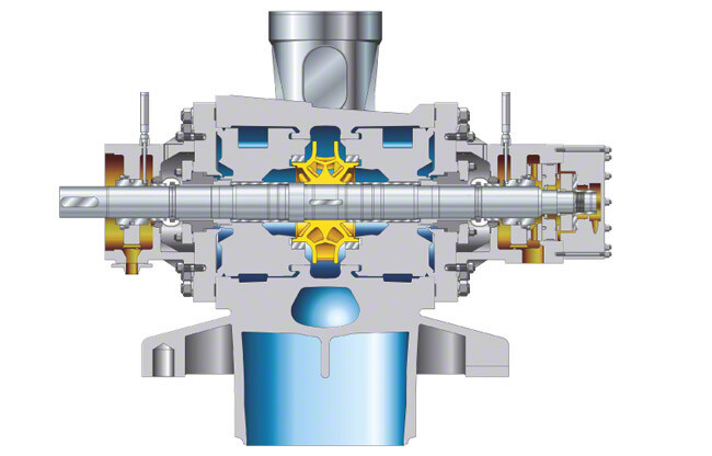
Project pressure-holding packaging parts are progressively supplanted by manufactured parts. For instance, such a feed siphon could be planned with a stream pace of around 4200 m3/h and a head of around 700 m at a rotational speed of 5300 rpm. See Fig. 5 Kettle feed siphon
Heads of reactor feed siphons are in the locale of 800 m for bubbling water reactors and 600 m for compressed water reactors. The stream rates are about two times as high as those of an equivalent kettle feed siphon in a fossil-fuelled power station.
Casing
For boiler feed pumps two variables must be considered in regards to the wall thickness of the packaging: the tension burdens and the different temperature conditions it necessities to endure. These two measures are fulfilled by taking on a high-strength ferritic packaging material which empowers the wall thickness to be kept sufficiently slight to stay away from any over-burdens because of temperature vacillations, yet of satisfactory thickness to ensure the imperative wellbeing against interior strain.
Barrel Casing
- The housings of barrel take out siphons and barrel packaging siphons are generally made of unalloyed or low-alloyed flexible manufactured steel. Store welding is involved on all surfaces in touch with the feed water to cover them with consumption and disintegration safe material.
- To weld the siphon into the channeling, a connector should be given if the materials of the spouts to be associated are from various material gatherings.
- The release side (release pressure containing) barrel cover is secured through huge non-forced studs. Fixing is given by a profile joint which is compressed simply by the overall strain (of up to a few 100 bar) with practically no outer powers following up on it. See Fig. 7 Heater feed siphon

Ring-area siphons
- The housings of ring-segment siphons are ideally made of fashioned chrome or carbon steel plated with austenitic (iron strong arrangement) material.
- The fixing component between the singular stage housings (see Stage) seals off by metal-to-metal contact, the singular housings being clasped together pivotally by tie bolts between the pull and release housings (see Siphon packaging).
- Warm shocks causing different warm extensions basically lead to extra loads on the tie bolts and fixing surfaces of the stage housings.
A typical element of barrel take out siphons and ring-segment siphons is that the more noteworthy the wall thickness, the more noteworthy the warm pressure brought about by warm shocks, which thusly lessens the help life of the siphon. The arrangement of infusion water at a strain arranged between the pull and release tension of the siphon is a successive prerequisite. This is dealt with by tapping water from one of the siphon phases of both barrel take out siphons and ring-area siphons.
Tapping a phase of a heater feed siphon
- On account of ring-segment siphons, a fractional stream at a middle of the road tension can undoubtedly be tapped through a tapping spout in one of the stage housings. See Fig. 5 Ring-segment siphon
- On account of barrel take out siphons, within the barrel is partitioned into three strain zones so a halfway stream at the necessary transitional tension can be opened straightforwardly to the outside. See Fig. 4 Barrel take out siphon
- The fixing capability is dealt with by a profile joint between the release and the tapping pressure, and by a metal-to-metal joint between the tapping and the bay tension. See Fig. 7 Evaporator feed siphon
- Particularly the profile joint permits an incredible level of relative movement of the fixing surface, as expected for any temperature shocks.
Rotor plan
The siphon shaft of heater feed siphons has a tiny static diversion as the heading are dispersed as intently as could really be expected, the shaft breadth is generally huge and the impellers are typically contracted onto the shaft (for elite execution). The siphon shaft is by and large unfeeling toward vibrations and moves along as expected (see Smooth running) with no outspread contact during typical activity. The center point measurement at the rear of the impeller is expanded and the impeller delta calculation is planned with a base width, to lessen the leftover pivotal powers (see Hub push) which must be consumed by the adjusting gadget.
The rotors of single-stage reactor feed siphons are considerably stiffer than those of evaporator feed siphons, and their static diversion is more modest than that of multistage heater feed siphons.
Axial thrust balancing
Some impeller game plans of evaporator feed siphons for regular power stations cause hub push at the impellers. See Figs. 10 to 12 Pivotal push
The greatness of this pivotal push relies upon the place of the working point, on the trademark bend, the rotational speed and how much wear on the inside clearances (see Controlled hole seal). Extra upsetting powers can emerge in case of unusual working circumstances, for example cavitation.
On bigger heater feed siphons the pivotal powers at the siphon rotor are adjusted through a water driven adjusting gadget through which the liquid took care of streams. The adjusting gadget is frequently joined with an oil-greased up push bearing (see Plain bearing). As this adjusting gadget ingests more than 90 % of the hub push, a generally little push bearing can be utilized. The adjusting gadget might include an offset circle with balance plate seat, or an equilibrium drum or twofold drum with the relating choke hedges.
Hub pushes emerging in reactor feed siphons with twofold section impeller (see Twofold pull siphon) are adjusted powerfully; lingering pushes are consumed by an oil-greased up push bearing. See Fig. 6 Heater feed siphon
Balancing of radial forces on the pump rotor
Spiral powers emerge from the heaviness of the rotor, mechanical unbalance or water driven outspread push. The outspread powers are adjusted by two oil-greased up spiral course as well as by choking clearances through which the liquid took care of streams in hub heading. Such choking clearances are situated at the impeller neck on the impeller bay side, or on account of multistage kettle feed siphons for customary power stations on the release side of the impeller (interstage shrub) and at the equilibrium drum. In the event that the rotor is in an off kilter position, a re-centring response power will be created in these clearances, which generally relies upon the strain contrast and the leeway calculation (LOMAKIN impact).
The LOMAKIN impact is seriously decreased when, because of unusual working circumstances, the feed water in the freedom isn't in a simply fluid stage (see Cavitation).
The hydrostatic activity of the clearances offers more to diminishing shaft diversion than the mechanical solidness does. The framework is planned so that working rate generally stays well away from the basic speed of the rotor, permitting water driven energizing powers (especially in low stream activity) to be caught up moreover.
An extra diffuser or a twofold volute can lessen outspread push. See Fig. 6 Volute packaging siphon
Shaft seal
Normal shaft seals for evaporator feed siphons are mechanical seals, drifting ring seals and maze seals. Organ packings are more uncommon nowadays. (Likewise see Shaft seal).
Heating up and keeping warm
Tra nsient or low stream working circumstances cause extra loads on heater feed siphons. This prompts extra anxieties and strains as well as to deformity of parts with different outcomes on their usefulness.
These days, practically all evaporator feed siphons should have the option to deal with both virus begins (high-temperature shock burdens) and semi-warm beginnings with next to no harm. In these beginning up methods hot feed water unexpectedly streams into the virus siphon, which brings about the internal parts warming up a lot quicker than the strain limit. Contingent upon the recurrence of starts and the angle bends of strain and temperature (load cycles) this can abbreviate the help life of the siphon.
On machines with especially thick walls the intensity will proliferate all the more leisurely in the thick-walled parts, hence expanding interior anxieties.
Contact between parts of the rotors and stator can't, by and large, be precluded as tight clearances are utilized as controlled hole seals This applies to the impeller neck on the impeller gulf side, the release side freedom between impeller, diffuser and interstage hedge as well as the offsetting gadget with a few choking clearances (contingent upon the plan).
Basic working circumstances, for example, the arrangement of fume rises, for instance, can't be totally kept away from in the bay line. Brief contact between the stator and the rotor prompts high unbalance powers in the thin clearances. Hence the material matches must be safe not exclusively to consumption and disintegration yet additionally particularly to wear (consolidating great enemy of seizure properties). Profiled chrome prepares and an extraordinary freedom math have demonstrated effective.
In working circumstances with an extremely low or zero stream, for example in the turning gear method of a turbine-driven evaporator feed siphon, temperature layers lay out in the liquid took care of, which might cause disfigurement of the rotors and, after a slight deferral, likewise of the non-pivoting parts. When the freedom holes are shut the rotor will be exposed to an essentially higher grating second, prompting over-burden of the turning gear and to halt of the siphon. For this situation, the temperature will never again be balanced at the rotor, which will additionally disturb the rotor deformity.
This can bring about a few hours of margin time for the siphon. Normally the main cure is to allow the machine to chill off to lessen or take out the basic temperature layers and the misshapening.
A few moves can be initiated to streamline the warm way of behaving of the siphon:
Keep away from huge contrasts in temperature in and on the siphon
- Thermally discrete the cool regions (shaft seal region) from the area through which the hot liquid passes (water powered framework and adjusting gadget) through a protection chamber framework; give a warm seal to forestall convection streams and extraordinary thermosleeves.
- Protect the beyond the siphon.
- Warm up or keep warm the siphon through constrained move through the machine, normally by means of choked pressure supply.
- Briefly or forever interfere with the cooling water supply in the space of the mechanical seal (auxiliary circuit).
- Limit the working boundaries for basic working circumstances (ΔT) (top/worst of the worst packaging) and additionally ΔT among packaging and feed water.
Lessen the impacts of enormous temperature contrasts
- Pivot the siphon in backup mode utilizing turning gear
- Utilize synchronized turning gear (limit or forestall genuine stop time)
- Channel water from basic warm regions.
Select great warm qualities while picking shaft seals
- Fit a non-reaching seal (drifting ring seal)
The above measures are every now and again utilized for barrel packaging siphons (barrel take out siphons) as their external aspects, wall thickness, drive (turbine with turning gear) and working modes are viewed as more basic than those of ring-segment siphons. In the event that conceivable, these actions are constantly computerized to shield the accessibility of the siphon set.
Minimum flow valve
A base stream valve (programmed distribution valve) guarantees a base stream rate and hence forestalls harm which could happen in low stream activity because of either an impermissible expansion in temperature prompting vaporization of the siphon content or low stream cavitation.


0 Comments
if you have any doubts, please let me know